A lathe needs a tumbler reverse gear for bidirectional cutting. Such a gear can be added by replacing the idler gear which connects the leadscrew via change wheels to the spindle by one or tow idler wheels. If these wheels are properly fitted, the leadscrew can be switched to left or right handed operation and can also be turned off.

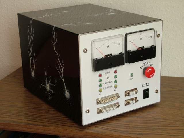
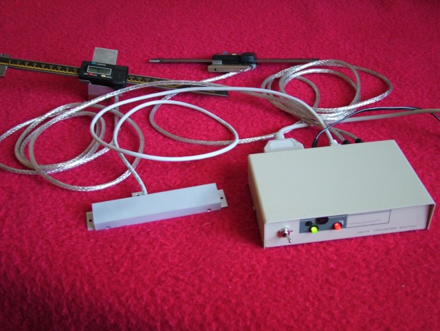
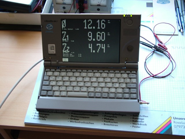
The same components that had worked well for retrofitting my milling machine were chosen for the lathe, i.e. digital readouts and a large display. Since the digital calipers for the Z axis are only 200 mm long, adjustable terminal clamping mechanisms were made which can be loosened and retightened in a different location when needed. Caliper travel and mounting space were limited. I therefore disassembled a DRO unit and put it into a custom enclosure without any display. A data transfer cable connects the DRO to the Yadro interface; software running on a Toshiba Libretto CT50 processes and displays the data. It is quite convenient to have the option of displaying either radius or diameter, of being able to zero the axes arbitrarily, of using offsets, and of entering the Z and Z0 values into calculations.
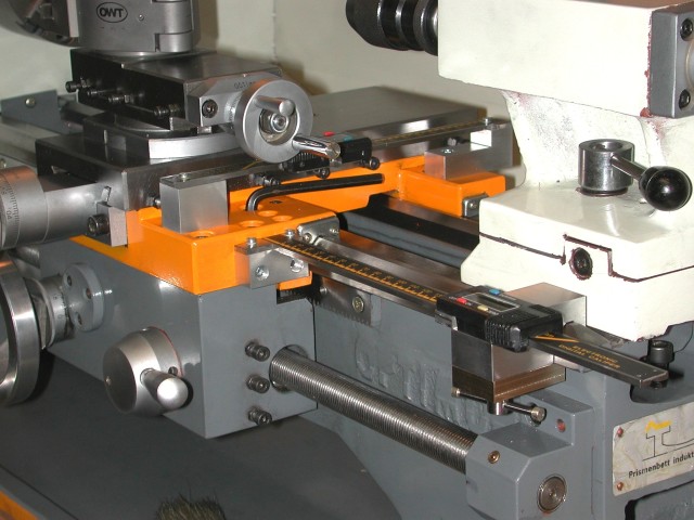

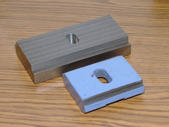
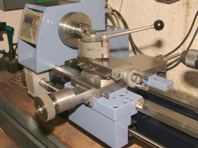
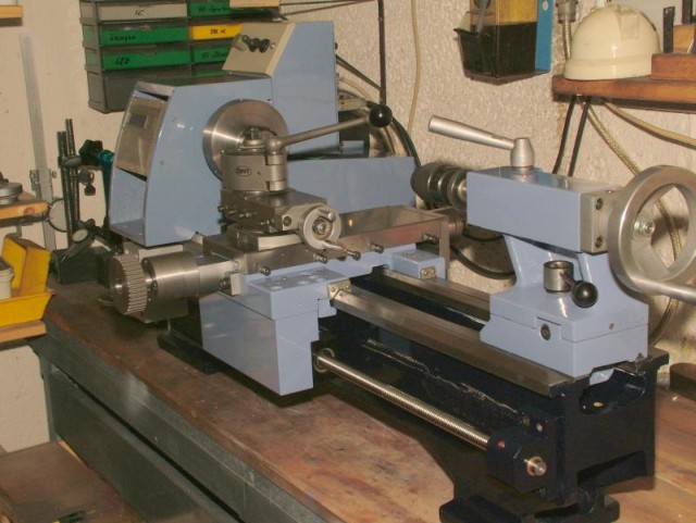
Replacing the tailstock baseplate by a larger one which I had machined to
tight tolerances resulted in a remarkable improvement. A lever attached to
a socket clamps the tailstock quickly and securely. A less than 90° twist
of this lever locks and unlocks the tailstock.

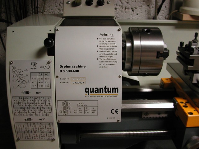
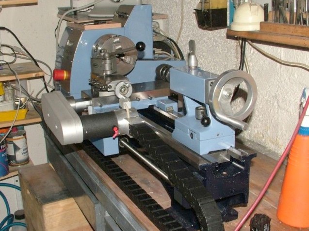
CNC Conversion of the Quantum 250x400
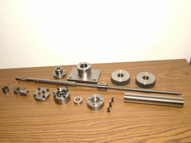
Ahead of time, I had machined all components required for retrofitting
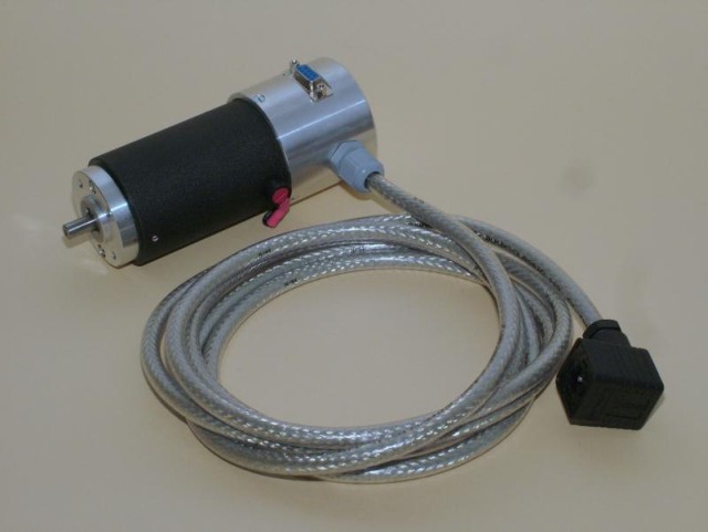
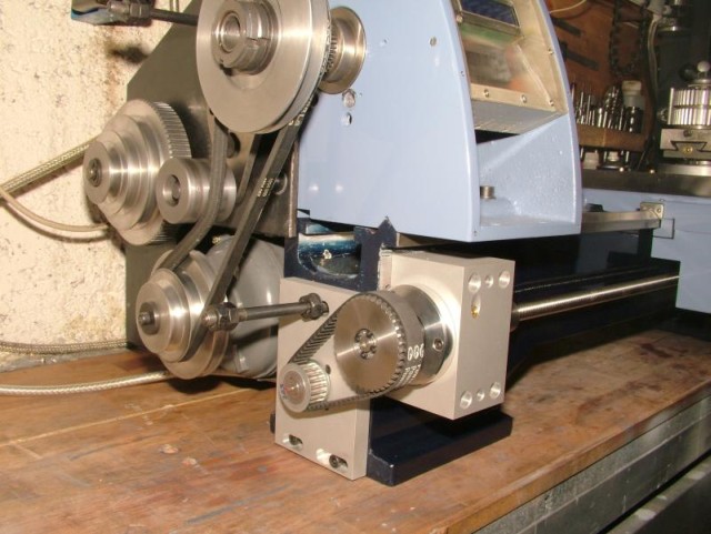
the lathe with ballscrews. For drive motors, I used E240 servo motors
connected via timing belts to achieve a 1:2 gear reduction. Retrofitting
the X axis was the most involved part. As there was insufficient room for
integrating the ballscrew into the cross slide, I mounted it on the back,
where it protrudes. A tube protects the ballscrew against chips.
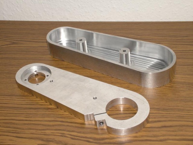
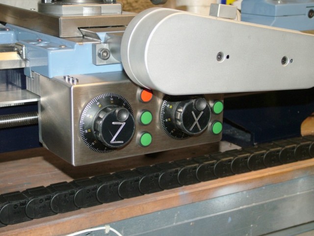
The apron was replaced by a solid aluminum enclosure which also houses the
Z ballscrew nut. This was a good place to mount the enclosure for the
manual controls, which allows me to operate the lathe by hand to machine a
part or another without a CNC program and without having to set up the
lathe for CNC operation.
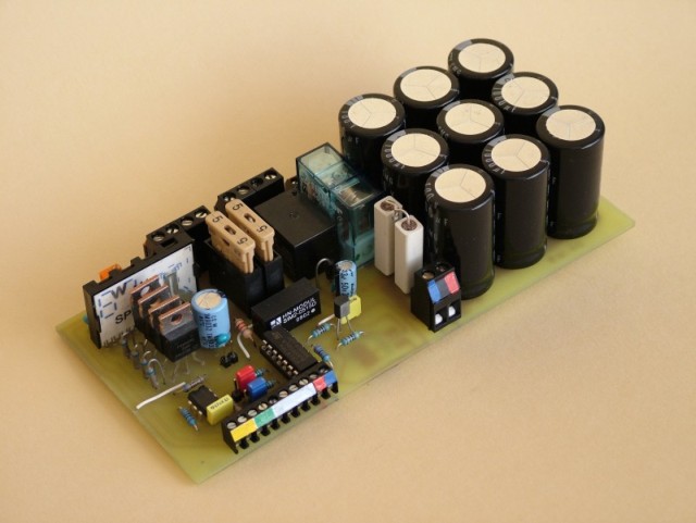
Once again I used UHU servo controllers. Some of the circuit board layouts were modified to be able to mount the PCBs in a compact computer case. The motors are run with 90 V.