| Upgrading the Wabeco F1210 -- Adding DROs
for all axes |
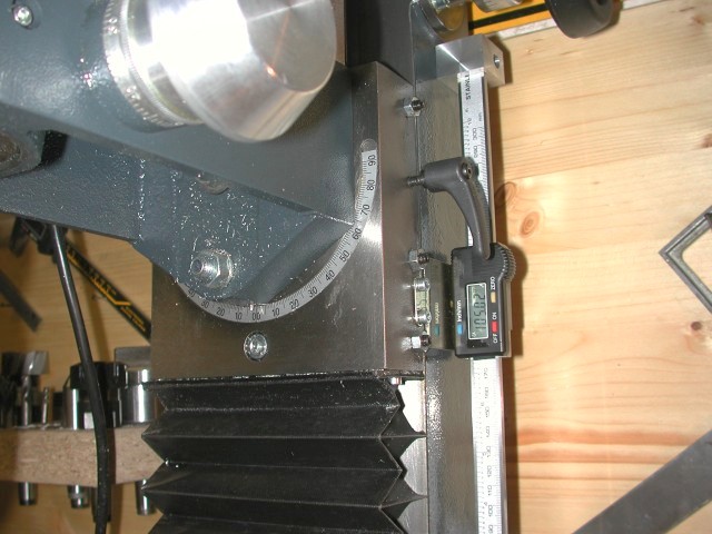
Retrofitting a vertical mill with digital radouts (DROs) significantly
expedites machining. The attachment brackets for the digital calipers were
easily machined. A large LED display improves readability. |
|
|
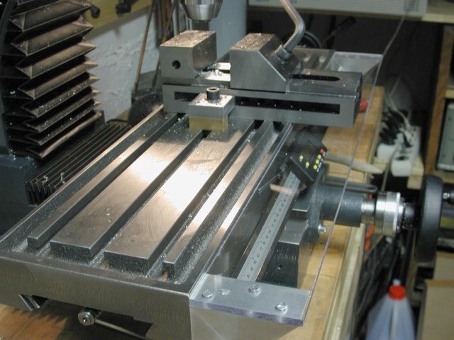
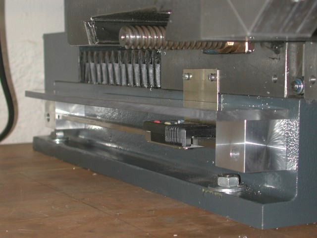
To prevent chips from falling onto the horizontal calipers,
I protected these with a polycarbonate cover.
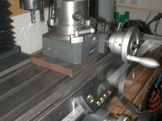
Since the rotary table handle was touching the cover, I had to elevate the
rotary table by adding a baseplate. |
|
|
The digital calipers worked very nicely. I just did not keep them for very
long, because they became redundant and had to go when I upgraded the mill
to CNC. |
Upgrading the Wabeco F1210 - Servo control retrofit (CNC, all
axes) |
In the past, I had attempted to attach stepper motors to my old Rotwerk
milling machine for a CNC retrofit. I got the X and Y axes to work,
but had to give up on the Z axis.
The photos below document how involved such an upgrade can get.
In the past, I had attempted to attach stepper motors to my old Rotwerk
milling machine for a CNC retrofit. I got the X and Y axes to work,
but had to give up on the Z axis.
The photos below document how involved such an upgrade can get. |
|
|
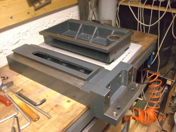
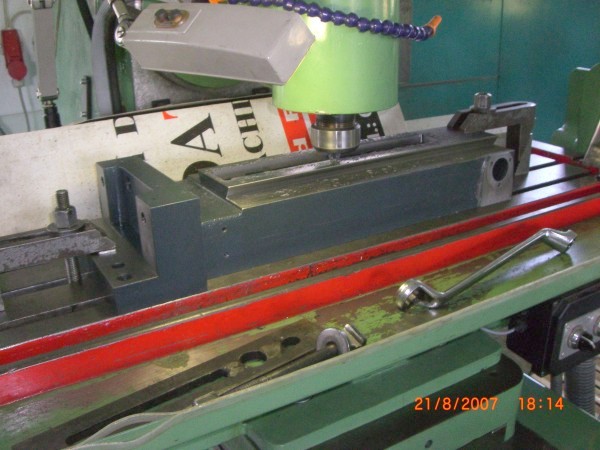
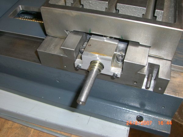
| To start out, I had to disassemble the entire mill, which required
several modifications because I wanted to replace the trapezoidal screws
by ball screws. A member of the German
CNC forum offered to help -- his help was really appreciated. The
above photograph shows the vertical column of my mill precisely aligned on
the T-table of a "real" milling machine which is shown milling a
sufficiently large slot to take up the ball screw nut. |
|
|
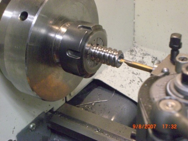
| Both sides of each ball screw required machining: I first center-drilled
and bored them on the lathe so that I could insert the original end
pieces, anchoring them with metal adhesive. I later realized that this
appraoch was not satisfactory. Bonding was not the issue -- it was
adequate, but the preload of the thrust bearings could not be adjusted
because the bearing preload is set against the timing belt pulley, the
bushing of which cannot take up the load. Incorrect distances to the
attachment points made me add spacer blocks to the ball screw nuts. |
|
|
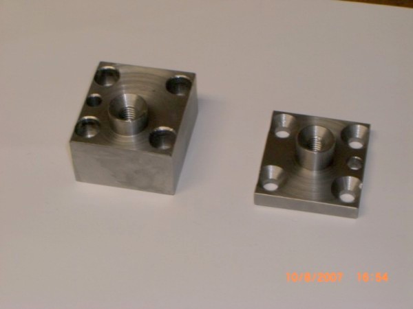
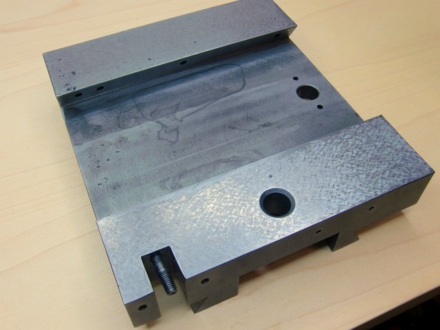
| There is not a lot of space left -- the clearance for the new ballscrews
would not have been sufficient if we had not enlarged the slot. Isel does
not sell wiper kits for the X axis ball screw nuts. Yet retrofitting
wipers is straightforward: Just machine a pair of mounts. I drilled the
original nuts to be able to push in insert nuts, which I anchored with a
metal adhesive. |
|
|
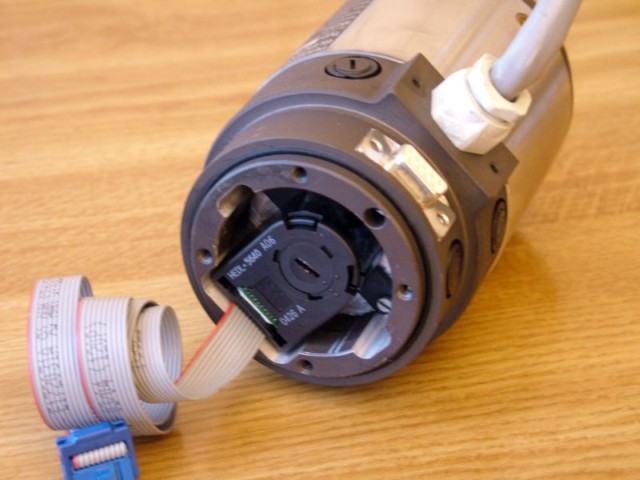
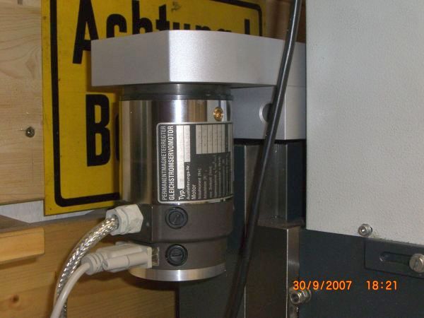
| The servomotors were retrofitted with encoders, replacing the resolvers.
For this, the motors had to be disassembled. In order to not demagnetize
the magnets, it is of utmost importance to insert a suitable iron tube
into the field frame while the armature is being extracted. |
|
|
|
|
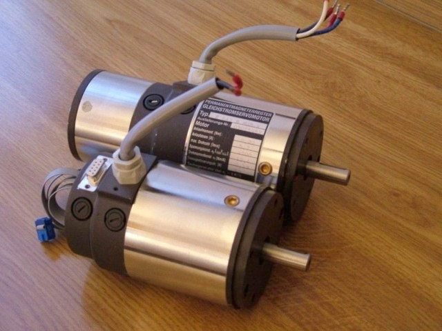
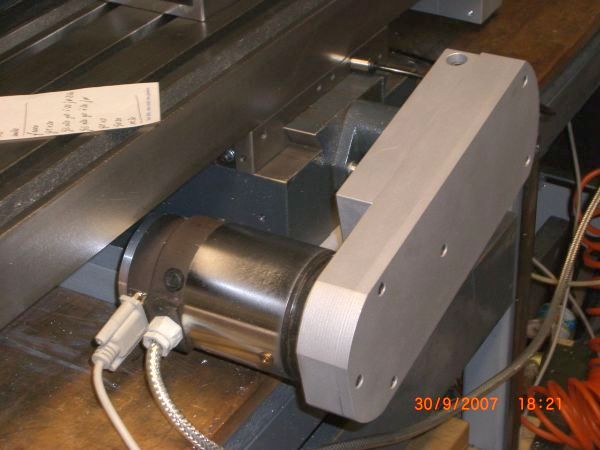
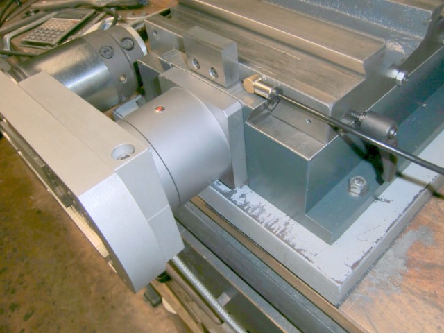
| All motors are mounted. The picture also shows the
respective enclosures for the timing pulleys and couplings. |
|
|
|
|
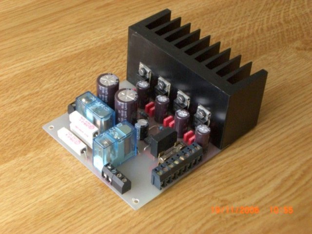
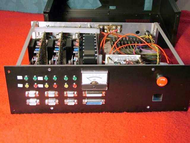
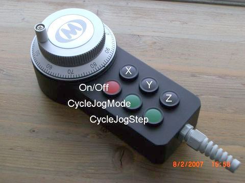
| A couple of electronic boards for the UHU
servo controller need to be soldered, a manual control has to built....
and the CNC mill is ready to run. |
|
|
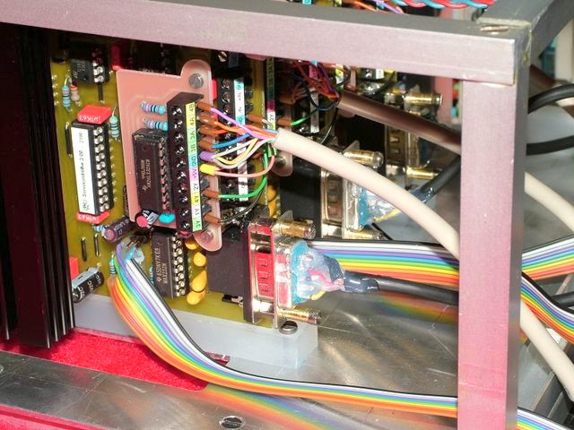
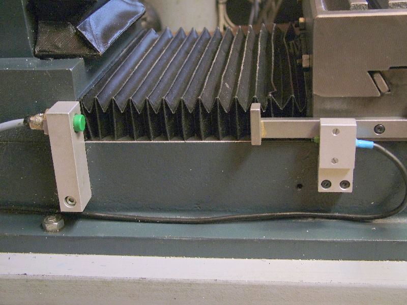
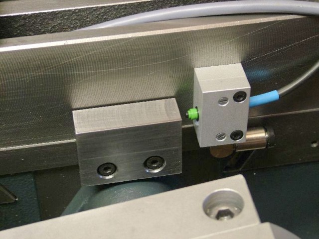
| Home and limit switches are essential: The motors are quite
powerful and would possibly damage the machine if they were to overrun the
limits of the axes. |
|
| When I had finished machining the first couple of
workpieces, an increasing amount of backlash became noticeable on the X
and Y axis. The cause was quickly located: The thrust bearings had become
loose because the bushings supporting the timing belt pulleys could
not take up the load. |
|
|
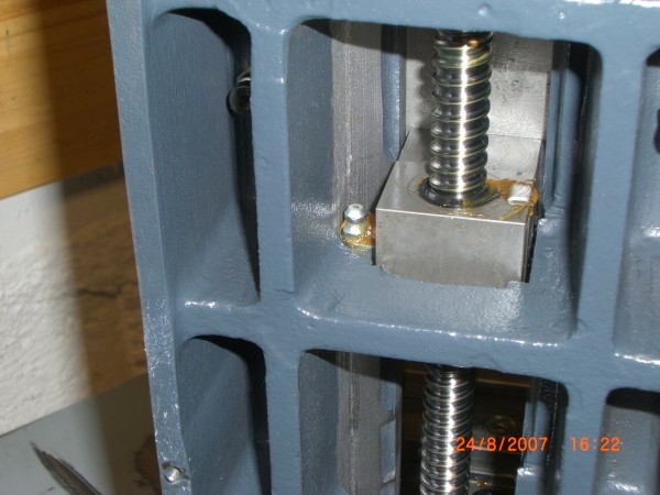
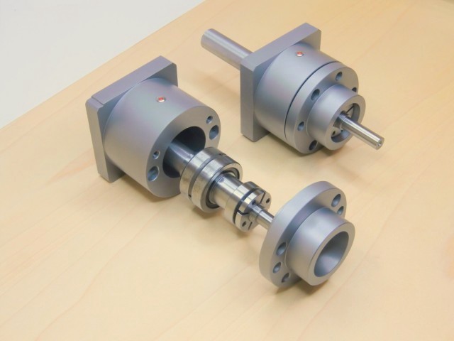
| These are the new thrust bearings with ZKLN axial angular
contact ball bearings preloaded inside the enclosure by a nut. After this
modifications, the timing belt pulleyonly has to transfer radial forces. |
|
|
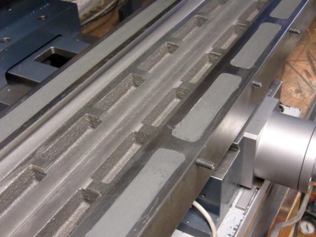
| The ways were beginning to show signs of wear, and wear
translated into less positional accuracy on the XY table. I re-scraped the
ways to make the entire surface take up the load instead of just the edges.
Several channels can be seen on the bottom of the T-table; the purpose of
these channels escapes me. These channels contribute to uneven wear on the
opposite side. I filled the channels with metal and metal polymer, added a
coating of Moglice and re-scraped these surfaces as well. The table moves
now much more smoothly and evenly. |
|
|
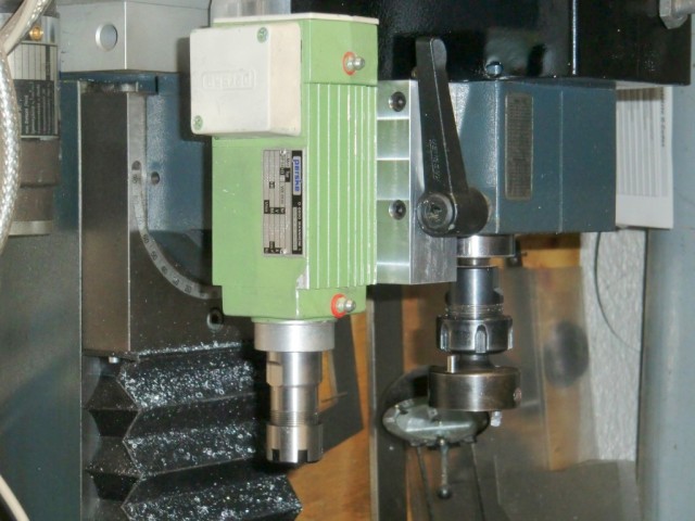
| As a last modification to the Wabeco milling machine, I
added a secondary high speed spindle. With a power of 200 W and an rpm of
17500, the spindle is quite suitable for engraving work. |